Purpose: intelligently route data between a source COM port and multiple targets.
Serial Router is alternative to Virtual Splitter which is providing more intelligent traffic routing and allows you to add Transformers to pre-process or post-process data sent to source or target ports.
It does not create any virtual ports and relies on either existing COM ports or virtual COM ports created by VSPE or other programs (such as Virtual Connector or Virtual Pair).
This device does not create new virtual serial ports.
This device is not accessible through API.

SmartRouter/Switch modes were added to address feedbacks/requests from HAM community.
These modes provide much better splitting experience for certain CAT protocols compared to Splitter.
Depending on selected mode (Fan-out, Router or Switch), the relevant data received from source COM port will be sent to all connected clients. If the connected application is not reading data, it will eventually fill output buffer and Serial Router will stop reading from Source COM port. To avoid that, you should let Serial Router know about such applications by unchecking "Allowed to receive data" checkbox in corresponding target COM port settings:
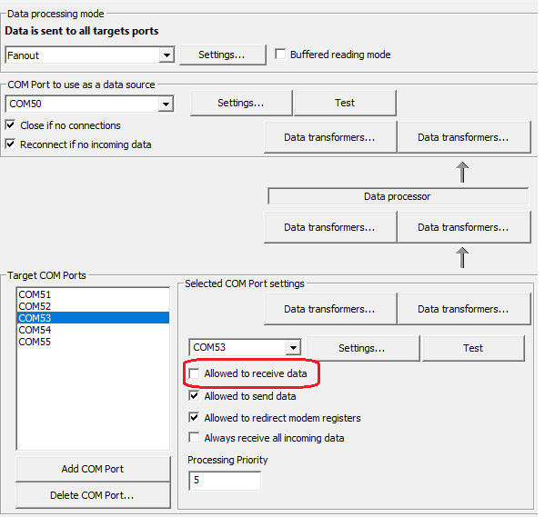
Uncheck "Allowed to receive data" for applications that connect but do not read data!
Serial Router works in one of the following modes:
- Fan-out: the same data processing the Splitter is using. Inbound data from source COM is redirected to all target COM ports. All data from target ports is redirected to source COM port. The advantage of Serial Router is that it can use data Transformers, and all traffic can be monitored in the VSPE Monitoring Tool.
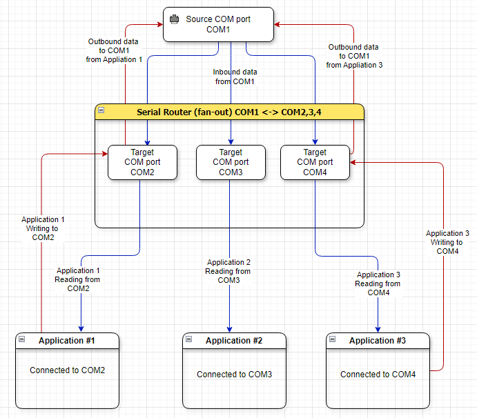
Serial Router (fan-out) data flow diagram
- Smart Router: in this mode the data from target ports is treated as Requests. The data from source port is treated as Response. Smart router will serialize requests and send those sequentially to source COM port. The responses will be sent to target port which issued request. To properly handle traffic, Smart Router needs to know what protocol is used. It can be configured in Settings.
- Switch: the same approach as Smart Router, but using different implementation which is applicable for certain protocols.
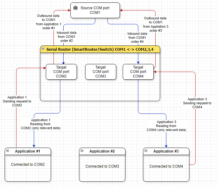
Serial Router (SmartRouter/Switch) data flow diagram
If "Detect virtual ports with multiple lanes" is checked, Serial Router will automatically detect all devices (such as Pair) with multiple lanes in Target ports and open all dedicated lanes. This feature was added to simplify configuring 3rd party applications with Router.
Example:
- Create Pair with 10 lanes (COM1 -> COM2).
- Create Serial Router. Add COM1 as target port (just once).
- Now, you can run up to ten 3rd party applications and connect them to COM2. All traffic will be going through serial router.
Lanes are using shared processing thread.
This means that if Pair device has a large number of lanes
and heavy traffic, delays may occur.
- Create Virtual Connector for every application (for example, COM2,3,4,5,6). You can also use Virtual Pair.
- Create Serial Router in desired mode
- Configure mode by clicking "Settings" button (select protocol if applicable to selected mode)
- Specify Serial Router source port and add target ports (COM2, 3, 4, 5, 6)
- Open COM2,3,4,5,6 with respective application
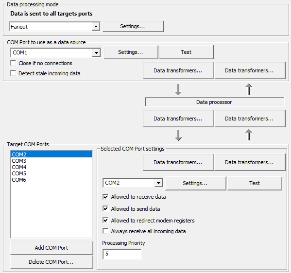
Serial router settings
- "Close if no connections": source COM port will be closed if there are no connections to Target ports (works only with Connector/Pair target ports).
- "Detect stale incoming data": if source COM port does not emit any data within 10-20 seconds, the Serial Router device will be automatically re-initialized. This can be useful to detect some unreliable hardware connected to Source port.
- "Detect virtual ports with multiple lanes": If the target port is a virtual port device (such as Pair) with multiple lanes, the Router will open all lanes.
- "Allowed to receive data" (for selected Target port): enabled Source -> Target data flow.
- "Allowed to send data" (for selected Target port): enabled Target -> Source data flow.
- "Allowed to redirect modem registers" (for selected Target port): modem registers are forwarded from Target port to Source port.
- "Always receive all incoming data" (for selected Target port): ignore routing/filtering rules for this target port and receive all data from source port. Applicable to SmartRouter.
- "Processing priority" (for selected Target port): The assigned priority is used when in SmartRouter or Switch mode to prioritize or de-prioritize requests from certain applications. High priority value instructs Serial Router to handle requests from selected Target port earlier.
If multiple clients are sending partially formatted commands (not full command, but by small chunks), there is a chance that this will result in write conflict when request from client1 is incorrectly merged with request from client2. To address that (for Serial Router is in fan-out mode) you should add Transformers to split data into consistently formatted chunks so that every chunk is a complete request. You can use
Wait for complete data transformer or another transformer. This will help to ensure that the data sent to source COM port is a complete packet and does not consist of small fragments mixed in random order from multiple clients.
Serial Router can contain multiple transformers which are applied sequentially before and after data has been processed. This can be used to modify data flow in any direction or for any port and sanitize input data to avoid write conflicts by sending incomplete data packets.
Processing data from source port to target ports
- In Serial Router settings, the data is flowing from top to bottom which is indicated by arrows pointing down. The data flow looks like this:
- Source COM port -> Transformer (one global instance) -> Data processor -> Transformer (new instance for every target) -> Transformer (one unique global instance for selected target) -> Target COM port
Processing data from target ports to source port
- In Serial Router settings, the data is flowing from bottom to top which is indicated by arrows pointing up. The data flow looks like this:
- Target COM port -> Transformer (one unique global instance for selected target) -> Transformer (new instance for every target) -> Data processor -> Transformer (one global instance) -> Source COM port
- See also:
-
